Layer 3 Switch Configuration for Inter-Vlan Communication for different networks?
what is gateway?
A gateway is a device or a software that connects two or more networks and allows data to flow between them. It can also perform functions such as protocol translation, data conversion, security filtering, or routing.
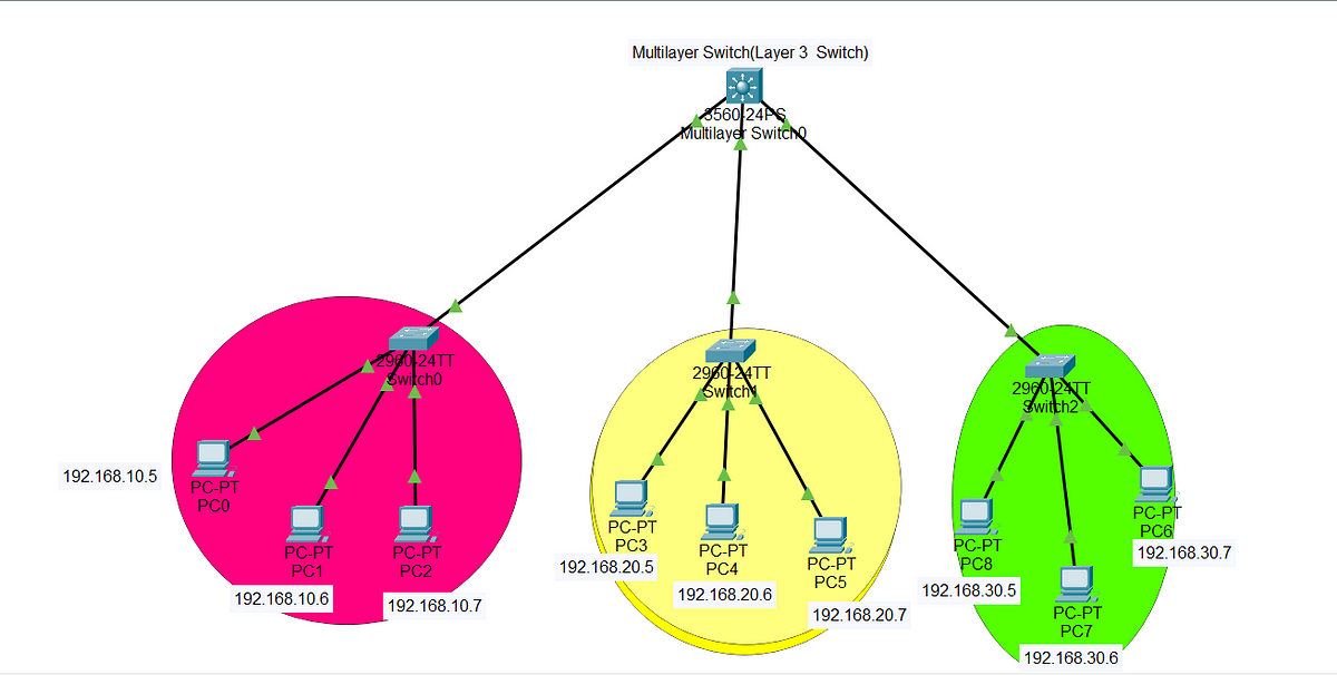
I have three layer 2 switches where different networks are installed. I have to configure a layer 3 switch for inter-VLAN communication.
First thing first, I will create three VLANs which I will assign IP Addresses to them which will act as default gateway for hosts connected to layer 2 switch.
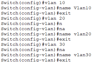
- To create VLANs we will use the command VLAN which is built in command for VLAN creation in switch.
- There is one VLAN already exist in switch is default VLAN for switch that can be used as a management VLAN.
Following commands are used to create three VLANs(10,20,30).
Switch>enable
Switch#config terminal
After running above commands, we are now in global mode which will we discuss in next lesson on switch basics.
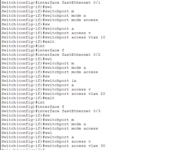
Now we have created three VLANs, so we will assign ports and IP Addresses to them.
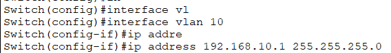

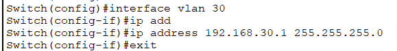
Now Run command IP routing on layer 3.

Now assigns IP Addresses to PC in the which are show in figure above at top with the default gateway as follows.
VLAN 10 PC’s — — — -> 192.168.10.1
VLAN 20 PC’s — — — -> 192.168.20.1
VLAN 30 PC’s — — — -> 192.168.30.1
Now our network is ready to get ping and send data between different PC's.


Comments
Post a Comment